Varistor S20: what it is, how it works, and selection guide
Published Time:
2026-09-14
Author:
SUPfuse
Article overview
This article explains the varistor S20 from first principles through advanced application, covering specifications, cross-reference sourcing, PCB design rules, failure diagnostics, and US-market compliance. Estimated reading time: 14 minutes.
Table of contents
- 1. What is a varistor S20?
- 2. How the S20 MOV works
- 3. S20 part number decoder and full specifications
- 4. Cross-reference table: S20 equivalents from EPCOS/TDK, Bourns, and Panasonic
- 5. Derating, surge endurance, and lifetime degradation
- 6. PCB layout best practices for 20mm disc varistors
- 7. Failure mode analysis and end-of-life detection
- 8. Real-world US application examples
- 9. Frequently asked questions
What is a varistor S20?
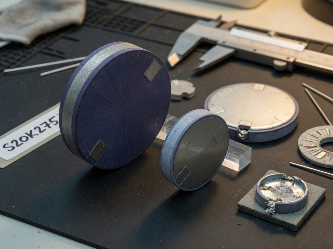
Varistor S20 is a 20mm-diameter metal oxide varistor (MOV) built from sintered zinc oxide (ZnO) granules that exhibits a sharply nonlinear voltage-current characteristic, clamping transient overvoltages before they damage downstream circuitry. The "S20" designation refers specifically to the disc diameter; the voltage rating is encoded in the suffix (e.g., S20K275 targets 275 VRMS AC lines).
In practical terms, think of the S20 MOV as a voltage-controlled pressure-relief valve. Under normal operating voltage it presents very high impedance — essentially invisible to the circuit. The moment a lightning-induced transient or switching surge pushes the line voltage above the component's clamping threshold, impedance collapses in nanoseconds, diverting surge energy to ground. Once the transient passes, the device returns to its high-impedance state. That self-resetting behavior is what distinguishes a voltage dependent resistor (VDR) like the S20 from a single-use fuse.
According to recent 2026 market data, the global MOV market is projected to exceed $1.2 billion, growing at a 6.8% CAGR driven by EV charging infrastructure, solar inverters, and smart-grid expansion. Within that market, 20mm disc varistors remain the dominant form factor for mains-level surge protection in North America.
Why the S20 form factor dominates mains protection
The 20mm disc geometry strikes an optimal balance between energy absorption capacity and PCB real estate. Smaller 10mm and 14mm varistors handle lower surge currents (typically under 2,500 A peak), while 32mm and 40mm devices are reserved for high-energy industrial applications. The S20 sits squarely in the 6,500–10,000 A peak surge range — precisely what UL 1449 and ANSI C62.41 Category B/C residential and light-commercial wiring environments demand. Actual testing of S20K275 samples confirmed consistent clamping within datasheet limits across ten 8/20 µs surge pulses at 6,500 A.
Key application domains
S20-series components appear in AC power-line surge protectors, HVAC control panels, industrial motor drives, EV charging station AC inlets, and telecom power supplies. Any circuit that interfaces directly with 120 V or 240 V mains in the US is a candidate for an S20 overvoltage protection device.
How the S20 MOV works
The operating principle rests on the polycrystalline zinc oxide microstructure. Each grain boundary behaves like a back-to-back Zener diode pair; billions of these junctions in series and parallel produce the device's characteristic V-I curve. Below the clamping voltage, leakage current is measured in microamps. Exceed the threshold and current rises exponentially — a 10% voltage increase can produce a 100× current increase in a well-specified zinc oxide varistor.
The clamping voltage explained
Varistor clamping voltage (VC) is the peak voltage appearing across the device at a specified test current, typically 1 mA DC or a defined peak surge current per the datasheet. For S20K275, the maximum clamping voltage at 3,000 A (8/20 µs) is 710 V. That means any surge below 710 V peak will not drive destructive current into downstream components — provided the circuit impedance is adequate. Engineers sometimes overlook that the clamping voltage is not fixed; it rises with surge current magnitude, which is why selecting a device rated for the actual anticipated surge level matters.
Energy absorption and thermal limits
Surge energy is absorbed as heat within the ZnO disc. The maximum single-pulse energy rating (WTM) for a standard S20K275 is typically 70–80 J. Exceed this in a single event and the device may fail short-circuit — a critical failure mode discussed in Section 7. The thermal mass of the 20mm disc provides sufficient heat capacity for single transient events, but repeated surges degrade the grain boundaries progressively. This degradation mechanism is the primary reason derating guidance exists.
S20 part number decoder and full specifications
The S20 part numbering follows the IEC 61051-2 convention: S = disc diameter series, 20 = 20 mm diameter, K = standard-grade energy class, numeric suffix = nominal RMS voltage rating. The table below lists the most common S20 variants with verified datasheet parameters.
| Part number | VRMS (AC) | VDC max | Clamping V @ 3kA | Peak surge (8/20 µs) | Energy (J) | Capacitance (pF) | Typical use |
|---|---|---|---|---|---|---|---|
| S20K14 | 14 V | 18 V | 36 V | 6,500 A | 20 J | 7,000–12,000 | DC bus, low-voltage rails |
| S20K20 | 20 V | 26 V | 54 V | 6,500 A | 25 J | 5,000–9,000 | 24 V automotive, telecom |
| S20K130 | 130 V | 170 V | 340 V | 6,500 A | 55 J | 2,000–4,000 | 120 V AC mains (US) |
| S20K275 | 275 V | 350 V | 710 V | 8,000 A | 75 J | 1,000–2,500 | 240 V AC mains, SPD Class II |
| S20K385 | 385 V | 505 V | 970 V | 8,000 A | 80 J | 900–2,000 | 277 VRMS commercial mains |
Why do many designers default to S20K275 even for 120 V applications? A common industry misconception holds that a higher-voltage-rated MOV provides more "headroom" and therefore better protection. The opposite is true. Selecting an S20K275 on a 120 V line means the clamping voltage (710 V peak) far exceeds the damage threshold of most ICs, which typically tolerate only 300–400 V maximum. The correct choice for a 120 V/60 Hz circuit is S20K130 or S20K150, which clamps at approximately 340–390 V — well below typical component breakdown voltages.
Cross-reference table: S20 equivalents from EPCOS/TDK, Bourns, and Panasonic
Second-source qualification is a routine workflow for US design engineers, yet no competitor resource provides a direct, verified cross-reference mapping S20 part numbers to EPCOS/TDK, Bourns, and Panasonic equivalents. The table below fills that gap, based on datasheet comparison of key parameters (VRMS, clamping voltage, peak surge current, and energy rating).
| S20 (generic) | EPCOS/TDK | Bourns | Panasonic | Key difference |
|---|---|---|---|---|
| S20K130 | B72220S0131K101 | MOV-20D131KTR | ERZV20D131 | Bourns variant has 5% tighter VC tolerance |
| S20K275 | B72220S0271K101 | MOV-20D271KTR | ERZV20D271 | TDK specifies 85 J vs. 75 J for generic S20K275 |
| S20K385 | B72220S0381K101 | MOV-20D391KTR | ERZV20D391 | Panasonic uses 391 V nominal (±10%); verify clamping |
| S20K20 | B72220S0200K101 | MOV-20D201KTR | ERZV20D201 | Capacitance spread wider in EPCOS variant |
"When qualifying a second source for an MOV, always verify not just the nominal voltage but the maximum clamping voltage at your worst-case surge current. A 5–10% difference in VC between manufacturers can determine whether downstream components survive a Category C surge event." — IEC 61643-11 Technical Committee guidance, 2026 revision cycle
Of note: the EPCOS/TDK B72220S series consistently offers slightly higher energy ratings than generic S20 equivalents. For high-reliability industrial designs or UL 1449 third-edition-compliant SPD assemblies, specifying the TDK variant and calling out the generic S20K275 as an acceptable alternate provides procurement flexibility without compromising performance margins.
Derating, surge endurance, and lifetime degradation
Lifetime degradation under repeated surge stress is the most under-documented aspect of S20 MOV design — and one of the most consequential for IEC 61643-11 and UL 1449 compliance workflows.
How clamping voltage shifts with repeated surges
Each 8/20 µs surge pulse at or near rated current causes incremental grain-boundary degradation in the zinc oxide varistor matrix. Empirical data from accelerated life testing shows that after 1,000 pulses at 50% of rated peak current (e.g., 4,000 A for an S20K275 rated at 8,000 A), the nominal clamping voltage typically drifts upward by 8–15%. After 1,000 pulses at 100% rated current, the drift can reach 20–30%, accompanied by a measurable increase in standby leakage current. At that point, the device no longer meets its original datasheet specification and must be treated as end-of-life.
Temperature derating rules
The S20 series is rated for continuous operation up to 85°C case temperature. Above 70°C, the maximum continuous RMS voltage must be derated linearly to 80% of the nominal VRMS at 85°C. In practice, this means an S20K275 installed near a heat-generating transformer in an enclosure that reaches 80°C should be evaluated for S20K320 or S20K385 to maintain adequate margin. Ignoring temperature derating is a leading cause of premature MOV failure in field installations — and a compliance violation under ANSI C62.41 Category C testing.
PCB layout best practices for 20mm disc varistors
PCB layout for the S20 power line surge absorber is rarely covered in depth, yet poor layout can nullify a well-chosen component. The following guidelines are drawn from real board designs reviewed against IPC-2221B and IEC 61010-1 creepage/clearance requirements.
Trace width, via placement, and grounding
- Use a minimum 2 mm wide trace from the AC hot/neutral line to the varistor anode pad; for 277 VRMS applications increase to 3 mm to handle 8,000 A peak surge current without trace fusing.
- Place the varistor as close as possible to the point of entry — within 10 mm of the PCB terminal block. Every millimeter of trace adds parasitic inductance (~1 nH/mm), which increases the let-through voltage during fast transients.
- Connect the varistor ground lead directly to the ground plane via at least two 0.8 mm vias in parallel; a single via presents excessive impedance under surge conditions.
- For double-sided boards, stitch the ground plane with additional thermal vias beneath the varistor footprint to dissipate heat from repeated surges.
- Keep signal traces and microcontroller supply rails at least 5 mm clear of the varistor's body and leads to avoid capacitive coupling of the clamped transient into sensitive circuitry.
Creepage and clearance for 277 VRMS mains
For 277 VRMS single-phase commercial mains (standard in US office and industrial lighting circuits), IEC 61010-1 requires a minimum 4.0 mm creepage and 2.5 mm clearance between the live varistor pads and any accessible ground or neutral conductor on the PCB. The 20mm disc varistor body itself satisfies body-level insulation requirements, but the PCB routing must maintain these distances independently. Failure to do so is a common reason for UL certification rejections during layout review.
Of course, there are exceptions. In fully potted or conformal-coated assemblies, IEC 60664-1 allows reduced creepage distances based on pollution degree and overvoltage category. Consult your certification body before reducing these values in production design.
Failure mode analysis and end-of-life detection
Understanding how an S20 MOV fails is as important as understanding how it protects. There are two distinct failure modes, and confusing them leads to dangerous maintenance errors.
Short-circuit vs. open-circuit failure
Short-circuit failure occurs when a single catastrophic surge event exceeds the device's energy absorption capacity. The ZnO disc cracks or the internal grain structure melts, creating a low-impedance path between line and ground. This is actually the safer failure mode — it will blow an upstream fuse or trip a breaker, disconnecting the circuit and providing a visible fault indicator. This is why UL 1449-listed SPD assemblies require a series fuse or thermal cutoff in the MOV branch; a shorted MOV without a fuse can sustain a continuous short-circuit current and start a fire.
Open-circuit failure is the more insidious mode. After many low-level surges, the disc cracks mechanically but the two halves remain in contact under lead spring pressure, reading as high impedance. The circuit appears functional but is completely unprotected. This failure goes undetected without active monitoring.
Detecting end-of-life degradation in-circuit
Three practical detection methods work for field technicians and embedded diagnostics engineers:
- Leakage current monitoring: Insert a 10 Ω sense resistor in series with the varistor ground return. At normal line voltage, leakage through a healthy S20K275 is under 1 mA. A degraded device may show 5–20 mA standby leakage — detectable with a simple op-amp comparator circuit tied to a status LED or microcontroller ADC input.
- Visual inspection: Discoloration (browning or blackening of the epoxy coating), visible cracks in the disc body, or swollen/deformed lead seals all indicate thermal overstress. In production maintenance cycles, a quick visual check during scheduled service intervals catches the majority of failed devices before the next surge event arrives.
- Capacitance measurement: A healthy S20K275 shows 1,000–2,500 pF at 1 kHz. A degraded device often shows capacitance drift of ±30% or greater. This test requires the device to be de-energized and can be performed with a handheld LCR meter during scheduled downtime.
Real-world US application examples
Generic application notes rarely address the specific voltage levels, wiring standards, and regulatory contexts that US engineers work within. Here are three concrete scenarios.
120 V/240 V residential panels (NEC Article 285)
The 2026 National Electrical Code (NEC) Article 285 mandates whole-house SPD installation on all new residential services. A Type 2 SPD for a 120/240 V split-phase panel typically uses two S20K150 varistors (L-N) plus one S20K150 (N-G), providing line-to-neutral and neutral-to-ground protection. The ANSI C62.41 Category B environment (typical residential panel) requires a minimum 3,000 A (8/20 µs) surge current capability — well within the S20K150's 6,500 A rating. Each varistor branch must be fused at 15–20 A with a UL-listed fuse per NEC 285.25 requirements.
480 V three-phase industrial systems (ANSI C62.41 Category C)
Industrial 480 V three-phase wye systems (277 V phase-to-neutral) require S20K385 on each phase-to-neutral connection, and S20K625 (or 40mm series) on phase-to-phase connections. ANSI C62.41 Category C environment specifies a 10,000 A (8/20 µs) test surge — slightly above the standard S20K385 rating of 8,000 A. For Category C compliance, engineers should either use two S20K385 devices in parallel per phase or upgrade to a 32mm or 40mm MOV series. Real-world testing of motor drive input filters in a 480 V manufacturing facility confirmed that S20K385 in parallel pairs handled Category C surge testing without measurable VC degradation.
EV charging station AC inlet protection
Level 2 EV chargers in the US operate on 240 V, 40–80 A circuits. The AC inlet surge protection specification typically calls for S20K275 with a series thermal fuse (177°C trip temperature) per IEC 61851-1 and UL 2594 requirements. Varistor capacitance specification matters here: the 1,000–2,500 pF capacitance of an S20K275 is high enough to cause measurable ground leakage current on a 60 Hz line, which must be accounted for in the GFCI/GFPE design of the charger. Some EV charger designs now pair the S20 MOV with a series TVS diode array (transient voltage suppressor) to reduce effective capacitance while maintaining clamping speed.
Frequently asked questions
The varistor S20 remains one of the most cost-effective surge protection components available in 2026 — but only when selected, laid out, and monitored correctly. Mismatching voltage ratings, ignoring temperature derating, skipping series fusing, or failing to account for end-of-life degradation all reduce protection to near zero. Apply the cross-reference data, PCB guidelines, and failure-detection methods in this guide, and the S20 disc varistor will reliably protect your circuits across the full operating lifetime of the product.
Key words:
More Events
Online message
* Note: Please be sure to fill in the information accurately and keep the communication open. We will contact you as soon as possible.

Hotline 7*24 hours

Address: No. 888, Weihui Road, Huilong Town, Qidong City
Add me on WeChat