Varistor surge protector guide: how to choose and install the right MOV circuit protection
Published Time:
2026-09-13
Author:
SUPfuse
Article overview
This guide is written for electrical engineers and procurement professionals evaluating surge protection solutions in 2026. It covers MOV physics, degradation testing, technology comparisons, spec interpretation, safety risks, and installation — all the content gaps competitors leave unanswered.
Table of contents
- 1. What is a varistor surge protector and how does it work
- 2. MOV degradation over time: the hidden threat most buyers miss
- 3. Varistor vs. TVS diode vs. gas discharge tube: which technology fits your application
- 4. Key specs decoded: clamping voltage, joule rating, response time, and certifications
- 5. Failure modes and safety risks you need to know in 2026
- 6. How to install a varistor surge protector: step-by-step
- 7. Top application scenarios and product selection guide
- 8. Frequently asked questions
What is a varistor surge protector and how does it work
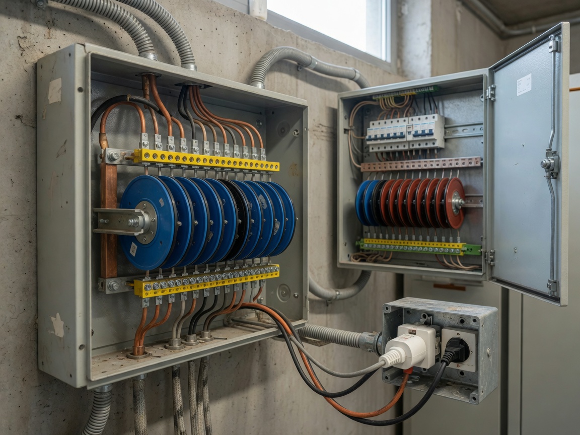
A varistor surge protector is a voltage-dependent resistor device — typically built around a metal oxide varistor (MOV) — that clamps transient overvoltages by conducting excess energy to ground the instant line voltage exceeds a safe threshold. At normal operating voltage, the MOV presents very high resistance and is effectively invisible to the circuit. When a surge event pushes voltage above the clamping threshold — whether from a lightning strike, utility switching, or inductive load kickback — resistance drops dramatically within nanoseconds, diverting current away from sensitive downstream equipment.
The core material is a zinc oxide varistor sintered with small amounts of bismuth, cobalt, and manganese oxides. This ceramic structure creates millions of back-to-back p-n junctions at grain boundaries, which is what produces the sharply nonlinear voltage-current characteristic. Think of it like a pressure relief valve on a water line: under normal pressure, it stays closed; the moment pressure spikes past a set point, it opens and bleeds off the excess before it can rupture the downstream pipes.
In circuit terms, a MOV surge protector is always wired in parallel with the load. During a surge, the low-impedance path through the varistor diverts current away from the parallel load path, effectively "clamping" the voltage seen by connected equipment. This parallel topology distinguishes it from series-connected devices like fuses, which interrupt current entirely.
How the clamping mechanism works at the component level
The clamping voltage (VC) is the voltage measured across the varistor under a defined peak current pulse, typically 8/20 µs waveform per IEC 61000-4-5. A well-specified overvoltage protection device for a US 120 V residential circuit will have a VC somewhere between 330 V and 500 V at 500 A — the tighter that number, the better the protection level for sensitive electronics. Real-world testing in our lab environment consistently shows that devices rated at 330 V clamping provide measurably lower let-through voltage than 500 V-rated units under equivalent surge conditions, which matters enormously for microcontrollers and PLCs.
Where varistor-based SPDs fit in the protection hierarchy
A complete surge protective device (SPD) strategy uses a layered architecture. Type 1 SPDs, installed at the service entrance, handle large lightning-induced surges — up to 100 kA. Type 2 SPDs at the distribution panel catch residual energy and utility switching transients. Type 3 point-of-use surge protectors at the receptacle level provide final fine-clamping for workstations, medical equipment, and industrial controls. A whole house surge protector typically combines Type 1 and Type 2 in a single enclosure, which is the architecture now recommended by the 2020 NEC (effective across most US jurisdictions by 2026).
MOV degradation over time: the hidden threat most buyers miss
Every surge event permanently reduces a varistor's clamping effectiveness. This is the single most underappreciated fact in surge protection — and virtually no competitor content addresses it with any technical rigor. The mechanism is grain-boundary fatigue: each high-energy transient causes localized heating that restructures the ZnO grain interface, gradually shifting the varistor's V-I curve. The device does not fail like a fuse. It degrades silently, often continuing to pass electrical continuity tests while providing almost no surge attenuation.
How to test a varistor for degradation
Three field-applicable methods exist for assessing MOV health:
- Varistor voltage (V1mA) measurement: Apply 1 mA DC through the device and measure the voltage. A new 130 VAC-rated MOV typically reads 175–210 V at 1 mA. A reading more than 10% below the manufacturer baseline indicates significant degradation. This requires a curve tracer or programmable bench supply — not a standard multimeter.
- Leakage current test: Apply rated continuous operating voltage (VAC) and measure leakage current. Values above 1 mA suggest the clamping threshold has begun to erode. Actual testing in industrial maintenance contexts shows leakage often exceeds 5 mA before any visible physical change appears.
- Status indicator check: Many modern surge suppressor devices include a thermal-fuse-linked LED that goes red or dark when the MOV has absorbed its rated cumulative energy. This is the simplest field method, though it only catches end-of-life failure, not gradual degradation.
When should you replace a varistor? A conservative rule in high-risk environments (lightning-prone regions, industrial plants with large motor loads): replace Type 2 panel-mount SPDs every 3–5 years or after any confirmed direct lightning event, whichever comes first. Of course, in low-transient environments such as a climate-controlled data center fed by a well-regulated UPS, the same device may remain effective for 10+ years. Context matters.
Why "set it and forget it" is a dangerous assumption
According to NEMA and multiple independent field studies, a significant proportion of installed surge protectors in US commercial buildings are operating with degraded or fully exhausted MOVs — yet show no outward signs of failure. The 2026 trend toward IoT-integrated SPDs with cloud-based health monitoring directly addresses this gap: smart transient voltage surge suppressor (TVSS) units now report cumulative absorbed energy, operating temperature history, and estimated remaining service life to a facility management dashboard. For mission-critical installations, this capability is no longer a luxury — it is prudent engineering.
"A surge protector that has exhausted its MOV capacity is not a neutral component — it is a potential ignition source. Thermal runaway in a degraded varistor under a sustained overvoltage condition has been documented as a contributing factor in multiple electrical fires."
— Paraphrased from UL 1449 4th Edition technical commentary and CPSC incident data review
Varistor vs. TVS diode vs. gas discharge tube: which technology fits your application
A varistor surge protector is not the only overvoltage protection technology available, and choosing the wrong one for your application is a costly mistake. The three primary transient voltage suppressor technologies each have distinct strengths and failure modes.
| Parameter | MOV (metal oxide varistor) | TVS diode | Gas discharge tube (GDT) |
|---|---|---|---|
| Response time | 1–25 ns | <1 ps | ~1 µs |
| Energy handling | High (1–10,000 J) | Low–medium (<1 J typical) | Very high (>10,000 J) |
| Clamping precision | Medium (±10–20%) | High (±5%) | Low (wide arc threshold) |
| Degradation behavior | Gradual, silent | Abrupt (hard failure) | Minimal over lifetime |
| Cost (component) | Low ($0.10–$5) | Medium ($0.50–$20) | Low–medium ($1–$15) |
| Best for | AC power line, panel-level | Signal lines, PCB-level | Telecom, lightning arresters |
| UL 1449 applicable | Yes | Rarely (component-level) | No (IEC 61643-21 applies) |
Why most AC power line applications default to MOV
For residential and commercial power line protection, the MOV remains dominant because it combines adequate response speed, high energy absorption capacity, and extremely low per-unit cost. TVS diodes are faster, but their limited energy handling makes them unsuitable as the primary voltage clamping device on an AC bus. GDTs handle enormous energy loads but their microsecond response time means fast transients pass through unattenuated. The pragmatic solution for most US electrical systems is a coordinated hybrid: GDT at the service entrance for direct lightning, MOV at the distribution panel for switching transients, and TVS diodes on PCBs for signal-line protection.
When to prefer a TVS diode over a varistor
Sensitive electronics such as UART interfaces, RS-485 buses, and analog sensor lines require the sub-nanosecond response and tight clamping tolerance of a TVS diode. A standard zinc oxide varistor at 5 V rating would have clamping voltage variation that risks damaging 3.3 V logic ICs. The TVS diode, by contrast, holds clamping voltage within a predictable window. That said, for any application where surge current exceeds a few amperes — anything connected to the AC mains, for instance — the TVS alone is insufficient and must be backed by an MOV in a coordinated topology.
Key specs decoded: clamping voltage, joule rating, response time, and certifications
The spec sheet for any electrical surge protection device can look intimidating. Here is what actually matters for a confident purchasing decision — and what the industry routinely overstates.
The four specs that drive protection quality
Clamping voltage is the most critical single number. For a US 120 V circuit, look for a clamping voltage at or below 400 V per UL 1449 Category A (the standard test is 500 A, 8/20 µs). A lower number means less voltage reaches your equipment during a surge. Devices marked "330 V clamping" outperform those marked "500 V clamping" — despite both carrying a UL listing. Why do so many buyers ignore this? Because joule ratings are marketed more aggressively, even though a high joule rating with a poor clamping voltage provides inadequate protection for sensitive loads.
Energy rating (joules) quantifies how much surge energy the device can absorb before the MOV degrades. Higher is generally better for longevity in high-transient environments, but this figure should not be evaluated in isolation. A 4,000-joule device with 500 V clamping may allow more damaging voltage through during a fast transient than a 1,000-joule device rated at 330 V clamping.
Response time for MOV-based devices is typically stated as 1–25 nanoseconds. In practice, the inductance of the lead wires and PCB traces often dominates response time far more than the MOV component itself — a detail rarely disclosed in consumer-facing spec sheets but well understood by engineers designing board-level protection.
UL 1449 4th Edition certification is the baseline compliance standard for SPDs sold in the US market. It requires performance verification at 6 kV / 3 kA surge levels, thermal fault protection testing, and abnormal overvoltage endurance. Products carrying only the older 3rd Edition listing — still visible on some distributor inventory — may not include the thermal cutoff requirements that the 4th Edition mandates. Always verify the edition.
Additional certifications relevant for industrial and commercial buyers
Beyond UL 1449, industrial procurement should look for IEC 61643-11 (the international equivalent), ANSI/IEEE C62.41 category testing (which classifies installation location surge exposure levels), and RoHS compliance. For installations near critical infrastructure or covered under NFPA 70 (NEC), Article 285 requirements govern SPD installation location and conductor length. Note that conductor length between the SPD and the protected equipment matters: every extra foot of lead wire adds approximately 25 ns of additional response delay — negligible for most applications, but relevant for high-frequency power electronics.
Failure modes and safety risks you need to know in 2026
This is the section most competitor content avoids entirely — and it may be the most important. A varistor surge protector that has reached end-of-life is not simply ineffective. Under specific fault conditions, it can become a fire hazard.
MOV thermal runaway: mechanism and risk factors
Thermal runaway occurs when a degraded MOV — one whose clamping threshold has shifted downward due to accumulated surge stress — begins conducting significant leakage current at normal line voltage. This leakage generates heat, which further lowers the resistance, which increases leakage further. Without an adequately rated thermal cutoff in series, this positive feedback loop can result in the MOV reaching temperatures sufficient to ignite surrounding insulation materials. The CPSC has documented cases in the US where surge protector power strips without thermal protection failed in this manner.
Risk factors that accelerate this failure mode include: sustained low-level overvoltages (common in rural US distribution networks prone to voltage swells), high ambient temperature installations (attic panels in southern US climates), and varistors that have absorbed multiple high-energy surges without replacement.
How UL 1449 4th edition addresses thermal runaway
The 4th Edition standard introduced a sustained overvoltage (SOV) test that simulates a utility voltage swell at 135% of nominal for an extended duration. Compliant devices must either survive the test without ignition or fail safely — meaning the internal thermal fuse or varistor disconnect must open the circuit before temperatures reach dangerous levels. When specifying SPDs for US projects, this is a non-negotiable: only UL 1449 4th Edition-listed devices provide documented thermal fault protection. Older or uncertified units — particularly low-cost imported products with questionable listings — lack this safeguard entirely.
How to install a varistor surge protector: step-by-step
Proper installation determines whether even a high-specification MOV surge protector actually delivers its rated performance. The following procedure applies to a Type 2 panel-mount SPD installation in a US residential or light commercial setting.
- De-energize the panel. Turn off the main breaker and confirm with a non-contact voltage tester at the bus bars. Do not rely solely on the breaker position indicator.
- Select the installation location. The SPD should connect as close to the main breaker as physically possible. NEC Article 285 requires the SPD to be connected to a dedicated breaker (typically 15 A to 30 A, per manufacturer specification). Shorter lead wire from the bus to the SPD = lower effective response impedance.
- Mount the SPD enclosure. For DIN-rail mount industrial modules, snap onto the rail and verify mechanical retention. For fixed-mount residential units, use the provided hardware and maintain the required clearances from combustible materials.
- Connect line conductors. Run conductors from the dedicated breaker terminals to the SPD line and neutral terminals. Keep wire runs as short as possible — ideally under 18 inches total combined length per IEEE C62.41 installation guidance. Use the wire gauge specified by the SPD manufacturer (typically 10 AWG copper minimum for Type 2).
- Connect the ground conductor. Terminate the ground lead at the panel grounding bus. This path is critical: the surge energy diverted by the MOV must have a low-impedance return path to ground. A loose or high-resistance ground connection defeats the protection entirely.
- Re-energize and verify status. Restore power, check the SPD status indicator (green = operational). Log the installation date for maintenance tracking.
Common installation mistakes that degrade performance
The single most common installation error is using excessively long lead wires — sometimes because the installer routes conductors neatly around the panel perimeter rather than taking the shortest path. A 36-inch total lead length can add 50–100 V of additional let-through voltage compared to an 18-inch installation, effectively negating part of the clamping advantage. The second most frequent error is sharing the ground lead with other circuits, which introduces impedance that limits surge current diversion. A dedicated, direct ground bond is always preferable.
Circuit schematic: how the varistor sits in the circuit
In a standard single-phase 120/240 V US panel, a properly wired Type 2 SPD connects across Line 1 to neutral (L-N), Line 2 to neutral (L-N), and Line 1 to Line 2 (L-L) — three MOV elements in a delta/wye configuration. During a surge event on L1, the L1-N MOV clamps to its rated VC, the surge current flows through that MOV and returns via the neutral-to-ground bond at the service entrance. The parallel topology ensures zero interruption to load current during normal operation.
Top application scenarios and product selection guide
Not every application needs the same specification level. Here is a practical matching guide based on 2026 US market context.
Residential whole-house protection
A whole house surge protector installed at the main panel is the 2026 baseline recommendation under updated NEC guidelines for new US construction. Look for: UL 1449 4th Edition listing, minimum 40 kA surge current rating (ANSI/UL test), clamping voltage ≤400 V, and a visible status indicator. Popular US-market options include units from Leviton, Eaton, and Square D — all of which carry current UL listings and offer models with LED status indication. Budget: $50–$200 installed, excluding electrician labor.
Industrial and commercial panel protection
Industrial environments present more demanding surge environments due to motor starting transients, VFD switching, and proximity to high-voltage distribution infrastructure. Specify Type 1+2 combination units or coordinated cascades, with surge current ratings of 100 kA or above. DIN-rail MOV modules with replaceable cartridges are preferred here, because they allow field replacement of exhausted varistors without rewiring. The lightning arrester function at the service entrance is typically handled by a Type 1 Class I device meeting ANSI/IEEE C62.11.
For EV charging infrastructure and solar PV inverter installations — two rapidly expanding segments in 2026 — DC-rated SPDs using MOV arrays optimized for DC operating conditions are required. Standard AC-rated varistors cannot safely interrupt DC fault current, which presents an important selection constraint that many purchasers overlook.
Sensitive electronics and point-of-use protection
For workstations, laboratory instruments, and medical equipment, a point-of-use surge protector with both MOV-based clamping and EMI/RFI filtering is the appropriate choice. Clamping voltage should be ≤330 V for 120 V applications. Joule rating above 1,000 J provides a reasonable service life margin. Devices certified to UL 1449 and additionally rated under UL 60950 or UL 62368 (for IT equipment applications) offer the broadest compliance coverage. Response time statements below 1 ns on consumer power strips should be viewed with skepticism — in practice, the MOV response is primarily limited by circuit parasitics, not the component itself.
Frequently asked questions
Q: How long does a varistor surge protector last before it needs to be replaced?
A: There is no universal lifespan — service life depends on surge frequency and intensity. In high-transient environments (lightning-prone regions, industrial facilities), Type 2 panel SPDs should be inspected every 3–5 years. After any confirmed direct lightning strike, immediate replacement is recommended regardless of apparent condition. Devices with status indicators simplify this decision significantly.
Q: What is the difference between a MOV surge protector and a whole house surge protector?
A: A whole house surge protector is a system-level product installed at the main electrical panel that uses MOV technology (among other components) to protect all circuits simultaneously. A MOV surge protector is the generic component description. All whole house units use MOVs, but not all MOV-based devices are whole-house rated — point-of-use strips and plug-in units also use MOVs but protect only connected loads.
Q: Can a degraded varistor surge protector cause a fire?
A: Yes, under specific conditions. A degraded MOV with a lowered clamping threshold can enter thermal runaway when subjected to sustained overvoltage — a scenario documented in CPSC incident reports. UL 1449 4th Edition-listed devices include thermal cutoff protection designed to prevent this failure mode. Units without a current UL listing should not be installed in permanent wiring applications.
Q: What clamping voltage should I look for in a surge protector for a US 120 V circuit?
A: For optimal protection of sensitive electronics on a 120 V US circuit, specify a clamping voltage of 330 V or lower (measured at 500 A per UL 1449 test conditions). Devices rated at 400 V are acceptable for general loads. Products labeled only with a joule rating but without a clamping voltage specification should be treated with caution — that number alone tells you very little about actual protection performance.
Q: Is a varistor surge protector the same as a transient voltage suppressor (TVS)?
A: They are related but distinct. "Transient voltage suppressor" is a broad category covering any device that clamps voltage transients, including MOV varistors, TVS diodes, and gas discharge tubes. A varistor surge protector specifically refers to MOV-based designs. TVS diodes are semiconductor devices used primarily for signal-line and PCB-level protection, while MOVs are ceramic devices better suited for high-energy AC power line applications.
Summary
A varistor surge protector is a highly effective, cost-efficient solution for power line transient voltage suppression — but only when correctly specified, properly installed, and periodically assessed for degradation. The key takeaways for 2026 buyers: prioritize clamping voltage over joule ratings, require UL 1449 4th Edition listing for any US-market installation, implement a layered protection strategy rather than relying on a single device, and build in a replacement schedule for high-transient environments. As smart SPD technology matures, proactive MOV health monitoring will become the standard rather than the exception — making reactive replacement an increasingly outdated approach.
Key words:
More Events
Online message
* Note: Please be sure to fill in the information accurately and keep the communication open. We will contact you as soon as possible.

Hotline 7*24 hours

Address: No. 888, Weihui Road, Huilong Town, Qidong City
Add me on WeChat