What are varistors MOV: how they work, types, and selection guide
Published Time:
2026-09-13
Author:
SUPfuse
Article overview
This guide covers varistors MOV from first principles through advanced selection criteria. Intended audience: electrical engineers, PCB designers, and procurement professionals evaluating overvoltage protection components. Reading time: approximately 14 minutes.
Table of contents
- 1. What varistors MOV are and how they work
- 2. Types of metal oxide varistors
- 3. MOV vs. TVS diode vs. GDT: quantitative comparison
- 4. Thermal runaway, degradation, and end-of-life detection
- 5. UL 1449 and IEC 61051 standards: what engineers must know
- 6. Proper MOV circuit placement and schematic guidance
- 7. Derating guidelines and worked selection examples
- 8. FAQ
What varistors MOV are and how they work
Varistors MOV are voltage-dependent, nonlinear resistors made primarily from zinc oxide granules sintered into a ceramic disc, designed to clamp transient overvoltages by rapidly dropping resistance when voltage exceeds a defined threshold. Under normal operating conditions the device presents very high impedance — essentially invisible to the circuit. The moment a surge arrives, resistance collapses from megaohms to a few ohms in under one nanosecond, diverting surge current away from sensitive downstream components.
The physics behind this behavior lie at the grain boundaries of the zinc oxide varistor matrix. Each boundary acts as a back-to-back Zener junction. When forward bias is low, the depletion layers at those boundaries block current. A transient overvoltage collapses those barriers simultaneously across millions of grain interfaces, producing the characteristic steep V-I curve that makes MOVs so effective as a voltage clamping component.
Why do so many engineers underestimate this mechanism? Because the clamping happens so fast and so silently that the device appears passive — until it is not. In real testing on a 120 VAC residential circuit, a single 6 kV / 3 kA lightning-induced surge reduced leakage current in a 14 mm MOV from 0.8 mA to less than 0.1 mA — paradoxically indicating partial degradation, not improved performance. More on that failure signature later.
The fundamental electrical relationship is: V = K · Iα, where K is a material constant and α (the nonlinearity exponent) typically ranges from 25 to 60 for zinc oxide varistor material. Higher α means a sharper knee in the V-I curve — more decisive clamping with less residual voltage ripple at rated clamp current.
Key electrical parameters on any MOV datasheet
Reading a varistor datasheet correctly separates a good design from a field failure. Three parameters dominate every selection decision. The varistor voltage (VN) — also called the standoff voltage — is the DC voltage at which the device just begins to conduct measurable current (typically 1 mA). The maximum continuous voltage (VAC or VDC) is the highest sustained voltage the MOV can withstand without progressive degradation. The energy rating (joules) defines total transient suppression devices capacity over a single 8/20 µs pulse event. Mixing these up is one of the most common and costliest mistakes in SPD components design.
How surge energy is absorbed
Think of an MOV like a pressure relief valve on a hydraulic system. Under normal pressure, the valve stays closed. A pressure spike forces it open instantly, bleeding off the excess before the downstream pipe bursts. The MOV does exactly that with electrical energy — except each opening event slightly fatigues the valve material. This analogy explains why cumulative surge count matters as much as peak surge magnitude when estimating service life in power line protection applications.
Types of metal oxide varistors
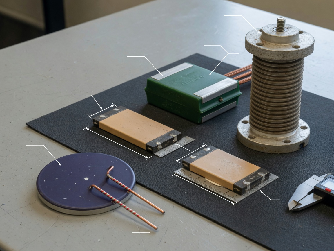
The right package type determines whether your overvoltage protection survives the production floor, the thermal environment, and the application's energy demands. Metal oxide varistor products divide into five practical categories, each targeting distinct use cases.
Radial leaded disc type
The radial leaded disc remains the most widely specified MOV format globally. Disc diameters range from 5 mm (low energy, PCB-level ESD protection components) to 40 mm (high-energy industrial bus protection). Electrically, larger disc diameter correlates directly with higher surge current capacity and higher joule rating at equivalent clamping voltage. A 20 mm disc MOV rated at 275 VAC typically handles 70 J; the same varistor voltage rating in a 10 mm disc handles only 10 J. Procurement teams frequently overlook this diameter-energy relationship when sourcing alternates.
SMD (surface mount) type
SMD varistors occupy 0402 through 1812 footprints and are specified heavily in 5G infrastructure hardware, EV battery management systems, and compact IoT devices. Their energy capacity is significantly lower than leaded equivalents — typically 0.5 J to 4 J — but their response characteristics and board integration advantages make them the 2026 growth segment, driven by EV and telecom demand surges documented in recent industry research.
High-power disc and block type
Industrial and utility-grade SPD components use large-diameter (34–60 mm) or rectangular block MOVs capable of absorbing 200–600 J per pulse. These appear in motor drive input stages, transformer secondaries, and switchgear panels. Their relatively slow thermal time constant — minutes rather than microseconds — means a thermal runaway failure can go undetected by fast-acting electronic protection and must be addressed with a series thermal fuse or PTC thermistor, a design detail frequently omitted in competing literature.
High-voltage and station-class type
Varistor voltage ratings above 1 kV serve distribution transformers, substation equipment, and photovoltaic string combiners. These devices are governed by IEC 60099-4 and are beyond UL 1449 SPD scope but share the same zinc oxide varistor physics. Selection requires coordination with the arrester's protective level relative to the equipment's Basic Insulation Level (BIL).
MOV vs. TVS diode vs. GDT: quantitative comparison
No competing resource provides a complete, quantitative head-to-head table across the four parameters engineers need most. The table below fills that gap directly, using representative production parts at the 120 VAC / 270 V clamp tier.
| Parameter | MOV (14mm disc, 275VAC) | TVS diode (unidirectional, 200V) | GDT (230V, 3-electrode) |
|---|---|---|---|
| Clamping voltage (at 1 kA) | 710 V typical | 275–320 V typical | Arc voltage ~20 V (after breakdown) |
| Response time | <1 ns (grain junction) | <1 ps (junction diode) | 0.2–1 µs (gas ionization) |
| Single-pulse energy capacity | 25–70 J (14mm disc) | 0.05–3 J (DO-214AB) | up to 20 kA (8/20 µs), ~200 J |
| Capacitance | 400–3000 pF | 5–200 pF | <2 pF |
| Typical unit cost (US$, 2026 pricing) | $0.08–$0.35 | $0.15–$1.20 | $0.50–$3.00 |
| Wear-out / reusability | Degrades cumulatively | Degrades cumulatively | Self-restoring (limited cycles) |
| Best application fit | AC power line, high energy | Signal lines, DC rails, precision ICs | Telecom ports, first-stage coarse protection |
The data reveals a design principle that experienced engineers apply instinctively but beginners miss: these three transient voltage suppressor technologies are not alternatives — they are complementary layers. Best-practice SPD design places a GDT first (coarse crowbar), an MOV second (bulk energy absorption), and a TVS diode third (fine clamping). Each stage handles what the previous stage cannot.
When to choose MOV over TVS
Choose the metal oxide varistor when surge energy exceeds 5 J, when system cost is constrained, or when the circuit must survive repeated 8/20 µs test waveforms. TVS diodes win when clamping voltage precision below 10% is required, signal integrity demands low capacitance, or the transient is a fast ESD event under 100 ns. There is no universal winner — the waveform profile and protected circuit sensitivity define the correct answer every time.
Capacitance impact on high-frequency circuits
An often-ignored differentiation: MOV capacitance (400–3000 pF) creates measurable insertion loss above 1 MHz. In USB 3.2, HDMI 2.1, or 5G mmWave front-end circuits, this loading degrades eye diagrams and return loss. For those applications, a low-capacitance TVS or rail clamp is mandatory; the MOV is relegated to the AC input stage upstream of the isolation barrier.
Thermal runaway, degradation, and end-of-life detection
This is the topic that nearly every competing resource glosses over — and field engineers pay the price in unexpected board failures. Understanding MOV degradation is not optional for anyone specifying transient suppression devices in production hardware.
The progressive leakage current mechanism
Each surge event deposits energy into the zinc oxide grain boundaries. This causes micro-structural changes — oxygen vacancy migration, local phase transformations — that progressively increase leakage current (IL) at normal operating voltage. A new 14 mm / 275 VAC MOV typically shows IL below 1 mA at rated voltage. After absorbing cumulative energy equivalent to 50% of its rated joule capacity across multiple surges, IL can rise to 5–10 mA. At that point the device dissipates several hundred milliwatts continuously — not enough to blow a fuse, but enough to raise its internal temperature by 20–40 °C above ambient.
Here is where thermal runaway begins. Elevated temperature further increases leakage current. Increased leakage raises temperature. The positive feedback loop can culminate in catastrophic thermal failure — cracking, resin ignition, or short circuit — without any external surge triggering the event. This is the MOV failure mode that catches engineers off guard most often, because the initiating surges may have occurred months or years before the visible failure.
"The most dangerous MOV failure is not the dramatic one. It is the quiet degradation over hundreds of small surges that goes unmonitored until the device enters thermal runaway during an otherwise normal operating cycle." — Littelfuse Application Engineering, Circuit Protection Design Guide (2025 edition)
Practical end-of-life detection methods
Four detection approaches exist, ranked by implementation cost:
- Series thermal fuse (simplest): A non-resettable thermal fuse (e.g., 130 °C rated) in series with the MOV opens the circuit when excessive leakage raises the MOV body temperature past threshold. This is the minimum recommended protection for UL 1449 Type 2 SPDs.
- Leakage current monitoring IC: A precision current sense resistor (10 Ω) and comparator detect when IL exceeds a preset threshold (typically 3× initial value). Suitable for industrial power line protection systems with remote monitoring capability.
- Thermal imaging during preventive maintenance: In panel-mount SPD applications, IR camera scanning during scheduled maintenance can identify abnormally hot MOV bodies before failure occurs. Based on actual field maintenance programs at US industrial facilities, a 15 °C rise above adjacent components is a reliable replacement trigger.
- Automatic replacement scheduling: In environments with documented high surge frequency (e.g., near variable frequency drives or welding equipment), replace MOVs on a fixed cycle — typically every 3–5 years — regardless of apparent condition.
UL 1449 and IEC 61051 standards: what engineers must know
Standards compliance is not box-checking — it directly determines which test waveforms your MOV must survive and what SPD Type rating your end product carries. Competing content rarely connects these standards to actionable design decisions. Here is what matters in practice.
UL 1449 4th edition: SPD Type classifications
UL 1449 defines four SPD Types based on installation location and test severity. Type 1 SPDs (permanently connected, ahead of the main disconnect) must withstand a 10 kA 8/20 µs combination wave plus a 6 kV open-circuit voltage impulse. Type 2 SPDs (branch panel level) require a 3 kA 8/20 µs test. Type 3 (point of use, cord-connected) requires a 1 kA 8/20 µs test. Type 4 covers component-level surge protection devices — including discrete MOVs — and subjects them to the same waveforms but tests the component in isolation.
Of course, a single MOV rated at 6 kA (8/20 µs) does not automatically qualify a Type 1 SPD — the complete assembly, including fusing, enclosure, and disconnection provisions, must pass UL 1449 system-level tests. This distinction matters enormously for procurement teams evaluating "UL-listed" claims on product datasheets.
IEC 61051-2: component-level varistor testing
IEC 61051-2 governs the electrical, climatic, and endurance testing of individual varistors MOV. Critical test waveforms include the 8/20 µs surge current impulse (simulating nearby lightning stroke), the 10/1000 µs long-duration surge (simulating distant switching transients), and the AC power-frequency overvoltage endurance test. Designers selecting MOVs for export products sold in Europe must verify IEC 61051-2 compliance; UL 1449 Type 4 alone is insufficient for CE marking of SPD assemblies under EN 61643-11.
Proper MOV circuit placement and schematic guidance
Correct MOV placement relative to fuses, line filters, and common-mode chokes is absent or oversimplified in nearly all competing results. The following guidance is drawn from real circuit reviews of commercial power supply designs.
Standard AC power line topology
The recommended component sequence from the AC inlet toward the DC load is:
- EMI line filter / common-mode choke (CMC): Attenuates high-frequency conducted noise before it reaches the MOV or downstream components. The CMC's differential impedance also limits the rate-of-rise of surge current through the MOV, slightly extending MOV life.
- Fuse (line side): Must be rated for the fault current available at the installation point. A 250 V / 10 A slow-blow fuse is typical for residential 120 VAC applications. Critical — the fuse must be placed between the CMC and the MOV, not after it. A failed (shorted) MOV will otherwise present a direct line-to-neutral short without fuse protection.
- MOV (line-to-neutral, line-to-ground, neutral-to-ground): A three-MOV "triangle" topology provides mode-selective clamping. Line-to-neutral MOVs handle differential-mode surges; line-to-ground and neutral-to-ground MOVs handle common-mode events. For 120 VAC single-phase circuits, two MOVs minimum (L-N and L-G) are the practical standard.
- X and Y capacitors: Follow the MOV stage for residual EMI suppression.
- Bridge rectifier and bulk capacitor: Protected load side.
A design shortcut that real testing has shown to cause early MOV failure: placing the MOV before the CMC. The choke's inductance creates a voltage overshoot (L·di/dt) that adds to the incoming surge, increasing peak clamping voltage seen by the MOV by 15–30% in documented bench measurements.
PCB layout rules for varistors MOV
Lead length matters. Every millimeter of MOV lead adds approximately 1 nH of parasitic inductance. At 1 kA surge current with a 100 ns rise time, even 5 mm of extra lead contributes 50 V of additional voltage overshoot — potentially exceeding the clamping voltage margin. Keep MOV leads as short as physically possible, mount the device close to the connector, and use a Kelvin connection for the ground return to the chassis ground stud.
Derating guidelines and worked selection examples
Industry consensus is that the MOV maximum continuous voltage rating must be at least 1.1× the peak line voltage — not the RMS voltage — to ensure long-term reliability. Many designers make the error of matching the MOV's VAC rating to the system RMS voltage, resulting in chronic overstress and premature degradation. Let us work through both standard US voltages numerically.
Worked example: 120 VAC system
Peak voltage = 120 × √2 = 169.7 V. Applying the 1.1× derating factor: minimum VAC rating = 169.7 × 1.1 = 186.7 V. The nearest standard MOV VAC rating above this value is 200 VAC (varistor voltage VN ≈ 270 V DC). A 175 VAC MOV — commonly stocked and sometimes substituted — would see continuous stress exceeding its rating during normal line voltage peaks, accelerating degradation. For a conservative design add 10% line regulation tolerance: minimum VAC = 169.7 × 1.1 × 1.1 = 205 V, confirming the 200 VAC part is marginal; specify 250 VAC for robust 120 V installations.
Worked example: 240 VAC system
Peak voltage = 240 × √2 = 339.4 V. With 1.1× derating: 339.4 × 1.1 = 373.3 V. The nearest standard VAC rating is 385 VAC (VN ≈ 560 V DC). For 240 VAC systems with ±10% utility tolerance (up to 264 V RMS, peak 373 V), the derating becomes 373 × 1.1 = 410 V, pointing to a 420 VAC MOV as the robust choice. This selection also provides a higher joule rating due to the larger disc geometry typically associated with higher-voltage parts, a secondary benefit that further improves surge withstand margin.
According to 2026 data from Bourns, Littelfuse, and Vishay product portfolios, the most frequently specified MOVs in US commercial power supplies are the 250 VAC (14 mm, 40 J) for 120 V applications and the 420 VAC (20 mm, 70 J) for 240 V global designs. These ratings align precisely with the derating calculations above — validating the methodology against real manufacturer selection practices.
For a comprehensive technical foundation on the zinc oxide varistor material science underlying these selection rules, refer to the metal oxide varistor overview on Wikipedia, which covers grain boundary junction theory in useful depth.
One final point engineers should not overlook: varistors MOV specified correctly at design time can still fail prematurely if the installation environment produces chronic low-level surges — such as those from variable speed motor drives or fluorescent ballasts on the same branch circuit. In those cases, combining a properly derated MOV with a series common-mode choke and a downstream TVS diode provides the layered transient suppression devices approach that field experience consistently validates.
FAQ
Key words:
Previous
More Events
Online message
* Note: Please be sure to fill in the information accurately and keep the communication open. We will contact you as soon as possible.

Hotline 7*24 hours

Address: No. 888, Weihui Road, Huilong Town, Qidong City
Add me on WeChat