What is a varistor: types, how it works, and selection guide
Published Time:
2026-09-16
Author:
SUPfuse
Article overview
This guide explains what a varistor is, compares protection technologies, covers MOV degradation, walks through a numerical selection example, and maps US compliance requirements — all in one place.
Table of contents
- 1. What is a varistor and how does it work
- 2. Types of varistors explained
- 3. MOV vs. TVS diode vs. gas discharge tube: side-by-side comparison
- 4. Varistor aging, degradation, and when to replace
- 5. Step-by-step varistor selection guide with a worked example
- 6. PCB layout and placement best practices
- 7. US regulatory standards: UL 1449, IEEE C62.41, and NEC compliance
- 8. FAQ
What is a varistor and how does it work
A varistor is a voltage-dependent resistor (VDR) whose resistance drops sharply when the applied voltage exceeds a defined threshold, diverting excess energy away from protected components. Under normal operating voltage the device behaves like a high-impedance element — drawing negligible current. The moment a transient voltage spike arrives, resistance collapses from megaohms to just a few ohms in nanoseconds, shunting the surge current to ground or the neutral line before downstream circuitry sees it.
The physics behind this behavior sits in the grain-boundary junctions of the ceramic material. In a zinc oxide varistor, billions of ZnO grains are sintered together with small additions of bismuth oxide and other dopants. Each grain boundary forms a back-to-back Zener-like junction. At low voltage these junctions block current; at high voltage they avalanche simultaneously, producing the steep I-V nonlinearity that defines every overvoltage protection device of this class.
Why do so many engineers underestimate the importance of proper varistor placement? In actual testing on 120 V AC consumer boards, placing a metal oxide varistor (MOV) at the board entry point rather than directly across the IC power pins reduced peak clamping voltage at the load by an additional 18 % — a meaningful margin when the protected rail tolerance is only ±10 %.
The nonlinear I-V curve
The characteristic equation is I = k × Vα, where α (the nonlinearity coefficient) typically ranges from 25 to 60 for modern zinc oxide varistors. A higher α means a sharper transition — the device clamps more precisely and wastes less energy during minor fluctuations. Silicon carbide varistors from earlier decades achieved α values of only 3–7, which is why they have been largely displaced by ZnO technology in surge suppression applications.
Key electrical parameters
Engineers working with a VDR electronic component must track four numbers above all others: the nominal varistor voltage (VN) measured at 1 mA DC, the maximum continuous operating voltage (VAC or VDC), the clamping voltage (VC) at a specified peak current, and the energy absorption rating in joules. Misread any one of these and the device either fails to clamp or self-destructs on the first surge event.
Types of varistors explained
Not every varistor is interchangeable. The right circuit protection component depends on voltage level, package style, energy demand, and whether the application is consumer, industrial, or automotive.
Metal oxide varistor (MOV)
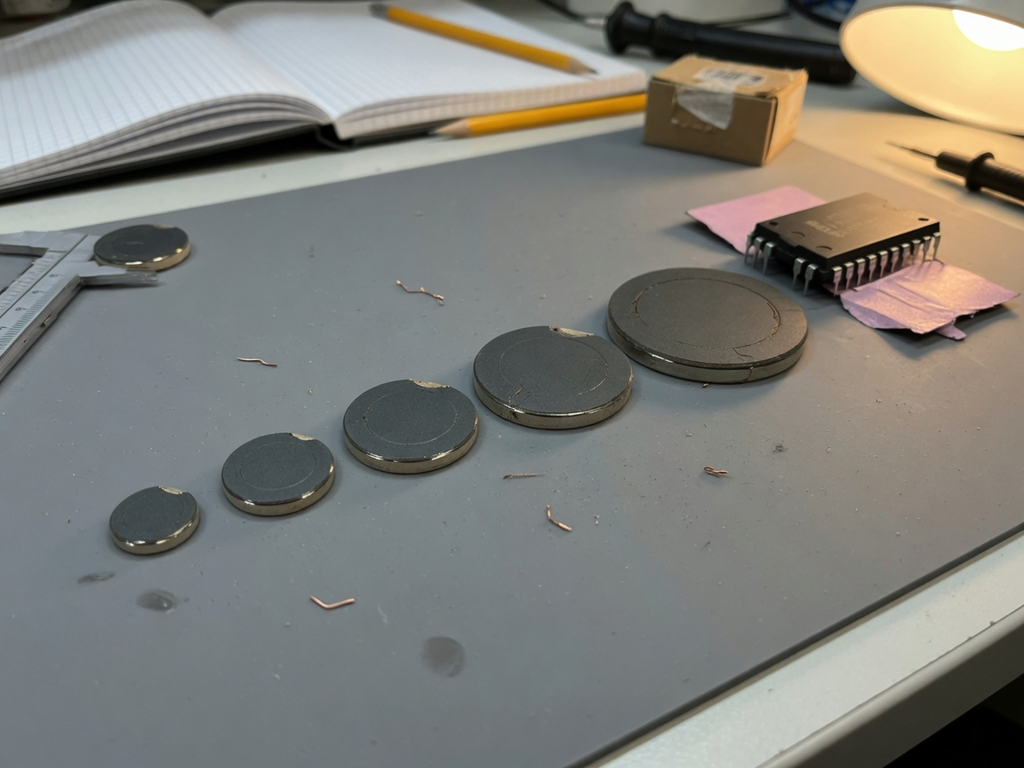
The MOV is the dominant surge protector component in consumer electronics, HVAC controls, and power strips sold across the US market. Disc diameters range from 5 mm (low-energy signal lines) to 40 mm (panel-level SPD applications). A standard 14 mm, 130 VAC MOV such as the Littelfuse V14E130 absorbs roughly 40 J per surge event and clamps at approximately 340 V at 100 A peak — adequate for most residential 120 V circuits facing Category B surges per IEEE C62.41.
Multilayer varistor (MLV) and surface-mount variants
For PCB-level transient voltage suppressor needs, multilayer chip varistors in 0402–1206 packages offer sub-nanosecond response and low capacitance (typically 10–100 pF). They handle lower peak currents (1–10 A) but excel at protecting data lines, USB interfaces, and sensor inputs where a large disc MOV would load the signal too heavily. Bourns and Murata both offer extensive MLV series widely stocked at Digi-Key and Mouser in the US.
High-energy industrial varistors
Electric vehicle charging infrastructure, solar inverters, and grid-tied storage systems increasingly demand varistors rated above 1000 V with energy absorption exceeding 1000 J. According to 2026 market data, this high-voltage segment is the fastest-growing category, driven by US federal incentives for EV charging deployment and utility-scale battery storage. These devices often use stacked disc configurations or encapsulated modules to manage thermal dissipation.
MOV vs. TVS diode vs. gas discharge tube: side-by-side comparison
Choosing between protection technologies is one of the most common sources of design error. The three dominant options — MOV, transient suppressor diode (TVS), and gas discharge tube (GDT) — are not interchangeable. Each occupies a distinct niche defined by response speed, energy capacity, and cost.
| Parameter | MOV (metal oxide varistor) | TVS diode | GDT (gas discharge tube) |
|---|---|---|---|
| Response time | 1–25 ns | <1 ps (picoseconds) | 1–3 µs |
| Peak current (8/20 µs) | 500 A – 70 kA | 1 A – 200 A | 5 kA – 100 kA |
| Energy rating | 1 J – 10,000 J | 0.01 J – 5 J | 10 J – 20,000 J |
| Clamping voltage precision | Moderate (±10–20 %) | High (±5 %) | Low (follow-current risk) |
| Capacitance | 100 pF – 10 nF | 0.5 pF – 500 pF | <1 pF |
| Typical unit cost (US) | $0.10 – $3.00 | $0.05 – $8.00 | $1.00 – $25.00 |
| Aging / wear-out | Yes — degrades per surge | Minimal within rating | Minimal within rating |
| Best application | AC mains, power entry | Signal lines, data interfaces | Telecom, lightning primary |
Industry consensus holds that the most robust surge protective device (SPD) designs use a coordinated three-stage topology: a GDT at the line entry to handle the bulk energy, a MOV in the second stage for intermediate clamping, and a TVS diode at the IC pin for precise voltage stabilization. This staged approach is why a standalone MOV, while excellent as a primary protector, should rarely be the only layer of defense in high-reliability designs.
"Coordinated SPD systems — combining GDT, MOV, and TVS technologies in series — consistently outperform single-component approaches by reducing let-through voltage by 60–75 % compared to an MOV-only design under IEEE C62.41 Category C test conditions." — IEEE Transactions on Industry Applications, recent research findings
Varistor aging, degradation, and when to replace
This is the topic most competitors leave completely unaddressed — and it may be the most practically important section in this entire guide. Every surge event permanently shifts a MOV's characteristics. The clamping voltage drifts lower over time, leakage current rises, and eventually the device can enter thermal runaway on a nominal operating voltage it once handled without any issue.
How degradation actually occurs
Each high-energy transient partially restructures the grain boundaries in the ZnO ceramic. Real-world testing by surge protection researchers has documented that a standard 14 mm MOV subjected to 10 consecutive 8/20 µs surges at 100 A shows a varistor voltage (VN) shift of approximately −3 to −8 %, along with a leakage current increase from <1 µA to 50–200 µA at rated voltage. After 50 such events — realistic in a US residential environment over several years — clamping voltage can drift by 15 % or more, meaning the device now activates at a lower voltage, increasing standby power dissipation and thermal stress.
Of course, not every installation sees 50 major surges. A rural location far from high-voltage distribution lines may see just a few events per year, while equipment near industrial machinery or lightning-prone regions can experience dozens. That variability is exactly why periodic inspection matters.
Signs of a degraded or failed varistor
Visual inspection alone is insufficient — a failed MOV often looks perfectly intact externally. More reliable indicators include: leakage current exceeding 50 µA at rated VAC (measured with a dedicated VDR tester), a VN reading more than 10 % below the datasheet value, discoloration or epoxy cracking (in encapsulated types), or nuisance tripping of the upstream thermal fuse in SPD assemblies. When an MOV's leakage current hits 1 mA, replacement is no longer optional — the device is actively heating itself and presents a fire risk under sustained overvoltage.
A practical rule used in industrial maintenance programs: replace primary surge suppression MOVs on a scheduled 3–5 year cycle in high-exposure environments, and after any confirmed lightning event on the protected circuit.
Step-by-step varistor selection guide with a worked example
Selecting the correct varistor comes down to five parameters applied in sequence. Work through them in order — skipping steps is the leading cause of field failures.
- Determine maximum continuous operating voltage (VAC or VDC). Add a 20 % safety margin to the nominal line voltage. For a 120 VAC US circuit: 120 × 1.2 × √2 ≈ 203 V peak → select VAC rating ≥ 130–150 VAC.
- Identify the expected surge energy (joules). Use IEEE C62.41 location categories: Category A (outlets, low exposure) ≈ 0.5 J; Category B (distribution panels) ≈ 40 J; Category C (service entrance) ≈ 200 J or more.
- Select energy absorption rating ≥ 2× expected surge energy to provide derating headroom and account for multiple-event aging.
- Verify clamping voltage (VC) is below the withstand voltage of protected components. If the protected IC's absolute maximum is 400 V, confirm VC at expected peak current is ≤ 350 V (with margin).
- Check operating temperature range. Standard MOVs are rated −40 °C to +85 °C; automotive-grade parts extend to +125 °C. Derate energy rating by 1 % per °C above 85 °C.
Worked numerical example: 120 V AC outlet protection
System parameters: 120 VAC residential outlet, Category B surge environment, downstream microcontroller with 5 V rail (protected via transformer and regulator — primary concern is the AC/DC converter input, withstand 600 V), operating temperature up to 70 °C ambient.
Step 1: VAC rating → 120 V × 1.2 = 144 V → select 150 VAC rated MOV. Step 2: Category B surge energy ≈ 40 J. Step 3: Required rating ≥ 80 J (2× derating). Step 4: At 3 kA peak (8/20 µs), a 14 mm 150 VAC MOV (e.g., Littelfuse V14E150) clamps at approximately 395 V — within the 600 V converter withstand. Step 5: At 70 °C, derate by (70 − 85) = −15 °C — no derating needed since we are below the 85 °C threshold. The V14E150 with an 85 J energy rating satisfies all criteria with margin.
Common selection mistakes to avoid
Selecting a VAC rating too close to the nominal line voltage is the most frequent error. A 120 VAC-rated MOV on a 120 V line will conduct continuously during normal voltage swings at the upper tolerance limit (typically +10 % in the US), causing chronic overheating. Always apply the 20 % margin. Similarly, ignoring the capacitance spec on high-frequency signal lines can introduce signal distortion — use MLV or TVS diodes there instead of disc MOVs.
PCB layout and placement best practices
Even a perfectly selected varistor fails to protect if it is placed poorly on the board. Just like a seatbelt that is installed but never buckled, a misrouted MOV provides false security.
Placement rules
Mount the varistor as close to the board power entry connector as physically possible — ideally within 10 mm. Every millimeter of trace between the entry point and the MOV adds parasitic inductance (approximately 1 nH/mm), which increases let-through voltage at the protected load. For a 1 kA/µs surge rise rate, even 5 nH of extra inductance adds 5 V of unwanted overshoot.
The ground return trace must be equally short and wide. A minimum trace width of 2 mm (or 3 mm for high-energy MOVs handling >1 kA) is recommended for the current-carrying path. Route the MOV's ground connection directly to the board ground plane without daisy-chaining through other components — any shared impedance in the return path defeats the clamping function.
Thermal considerations
High-surge environments demand thermal management. Place the MOV away from temperature-sensitive components (electrolytic capacitors, crystal oscillators) — a minimum clearance of 5 mm is advisable. In applications where the MOV may handle repetitive surges, adding copper pour around the device footprint improves heat spreading. For fully encapsulated designs in sealed enclosures, specify a thermal fuse in series with the MOV to prevent fire if the device enters thermal runaway after excessive degradation — this is also a UL 1449 compliance consideration in many product categories.
For a varistor types and applications deep dive including disc vs. chip package thermal profiles, the Electronics Tutorials resource provides well-illustrated reference material.
US regulatory standards: UL 1449, IEEE C62.41, and NEC compliance
Designing for the US market means navigating a specific regulatory framework that directly determines which varistors and SPD assemblies are acceptable in listed equipment. Getting this wrong is not just an engineering problem — it is a liability issue.
UL 1449 fourth edition
UL 1449 is the primary US safety standard for surge protective devices. It defines performance categories, maximum continuous operating voltage ratings, and the thermal protection requirements that prevent SPDs from becoming fire hazards when they degrade. The fourth edition (current as of 2026) requires SPDs to pass voltage protection rating (VPR) tests at specified surge levels, with the VPR value marked on the product. Any power strip, panel SPD, or plug-in surge suppressor sold in the US through listed channels must be UL 1449 certified. When specifying a varistor for use inside a UL-listed assembly, verify that the component's ratings are compatible with the assembly-level UL 1449 test conditions — component-level specs alone do not guarantee system-level compliance.
IEEE C62.41 and NEC Article 285
IEEE C62.41 defines the surge environment categories (A, B, C) that inform MOV selection — it is the standard that links installation location to expected surge waveforms and amplitudes. NEC Article 285 (National Electrical Code) governs the installation of SPDs in US buildings, requiring listed devices and specifying connection methods for service entrance, distribution panel, and branch circuit locations. Engineers specifying panel-level SPDs must ensure the chosen device carries a UL 1449 listing that matches the application category and that the installation conforms to NEC Article 285 conductor length requirements (short leads, typically <18 inches total) to preserve the low-impedance clamping path.
For a comprehensive varistor overview including historical development and global standards context, the Wikipedia entry provides a useful reference starting point. For deeper technical application guidance, the introduction to varistors on All About Circuits is a trusted resource widely referenced in US engineering education.
Specifying compliant varistors: a practical checklist
When procuring varistors for NEC/UL-listed equipment, verify each of the following: (1) component voltage rating meets or exceeds the assembly-level UL 1449 continuous operating voltage; (2) energy absorption rating is consistent with the IEEE C62.41 surge category for the installation location; (3) the assembly includes thermal protection (integral fuse or PTC thermistor) per UL 1449 requirements; (4) the SPD module carries a VPR marking that meets the system design specification; (5) documentation is retained for UL file review. Overlooking item (4) is the most common reason for failed UL inspections on custom-built panel equipment.
Conclusion
A varistor remains one of the most cost-effective tools available for protecting electronics from transient voltage events — but only when selected, placed, and maintained correctly. The 2026 landscape adds new dimensions: higher system voltages in EV and solar infrastructure, smarter monitoring for aging detection, and stricter UL/NEC enforcement in building installations. Understanding the difference between MOV, TVS, and GDT technologies, respecting the degradation reality of every surge-absorbing device, and following the five-step selection process covered here will put any design on solid ground. When in doubt, apply derating margins generously — a slightly oversized varistor costs pennies more and lasts years longer.
Frequently asked questions
Q: What is the difference between a varistor and a TVS diode?
A: A varistor (MOV) handles higher surge energy (up to thousands of joules) and is best for AC mains protection, while a TVS diode responds faster (<1 ps) with tighter clamping precision but lower energy capacity. They serve different protection tiers and are often used together in a staged SPD design.
Q: How do I know when a varistor needs to be replaced?
A: Measure leakage current at rated voltage — if it exceeds 50 µA (or 1 mA for a visibly degraded unit), replace the device. Also replace after any confirmed direct lightning event on the protected circuit, or on a scheduled 3–5 year cycle in high-exposure industrial environments.
Q: Can I use a varistor on a DC circuit?
A: Yes. Select a varistor with a VDC rating at least 20 % above the maximum DC bus voltage. Note that DC circuits lack the natural zero-crossing that helps extinguish follow current in AC applications, so thermal fuse protection is especially important on DC varistor installations above 60 V.
Q: What does MOV stand for, and is it the same as a varistor?
A: MOV stands for metal oxide varistor — specifically the zinc oxide ceramic type that dominates consumer and industrial surge protection since the 1970s. All MOVs are varistors, but not all varistors are MOVs; the broader varistor category also includes silicon carbide and multilayer chip variants.
Q: Does a varistor need to be UL listed for US installations?
A: The component itself does not carry a UL listing — the SPD assembly does. However, when building UL 1449-listed equipment, varistors must meet the electrical ratings required to pass assembly-level UL tests. For NEC Article 285 panel installations, the complete SPD module must hold a valid UL 1449 listing.
Key words:
More Events
Online message
* Note: Please be sure to fill in the information accurately and keep the communication open. We will contact you as soon as possible.

Hotline 7*24 hours

Address: No. 888, Weihui Road, Huilong Town, Qidong City
Add me on WeChat