Silicon carbide varistor guide: types, applications, and how to choose the right one
Published Time:
2026-09-17
Author:
SUPfuse
Article overview
This guide provides a technically rigorous examination of silicon carbide varistors for electrical engineers in the component selection and system design phase. It covers operating principles, device types, quantitative specification comparisons, application case studies, failure analysis, and US compliance requirements — all updated for 2026.
Table of contents
What is a silicon carbide varistor?
A silicon carbide varistor is a voltage-dependent resistor made from sintered silicon carbide (SiC) granules that sharply reduces its resistance as applied voltage rises, providing overvoltage protection and surge suppression in electrical circuits.
More precisely: silicon carbide varistor is defined as a nonlinear resistor whose current-voltage characteristic follows a power-law relationship (I = kVα), where the nonlinearity coefficient α typically ranges from 3 to 7 for SiC-based devices. This behavior makes it fundamentally different from a linear resistor and positions it as a core overvoltage protection device in high-voltage systems.
The term is often used interchangeably with "SiC varistor," "silicon carbide surge protector," or "silicon carbide lightning arrester component." In the broader taxonomy of protective components, it belongs to the family of voltage-dependent resistors (VDRs), alongside metal oxide varistors (MOVs) and zinc oxide (ZnO)-based devices. Understanding where SiC fits within this family — and where it clearly outperforms alternatives — is the first task for any engineer evaluating surge protection for high-voltage applications.
According to 2026 market data, the global varistor market is valued at approximately $1.4 billion, with a projected CAGR of 6.2% through 2028 (MarketsandMarkets). SiC-based overvoltage protection devices account for more than 40% of applications in power systems exceeding 10 kV — a figure that underscores their continued relevance despite the widespread adoption of ZnO technology in lower-voltage segments.
How silicon carbide varistors work: the nonlinear resistance mechanism
The core operating principle is straightforward: a silicon carbide varistor behaves as a high-resistance element under normal operating voltage, then transitions rapidly to a low-resistance state when voltage exceeds a defined threshold — clamping the transient and diverting surge current away from sensitive components.
The grain-boundary conduction model
At the microstructural level, the nonlinear behavior originates from potential barriers formed at the grain boundaries between SiC particles. Under low voltage, these barriers restrict electron flow, yielding high bulk resistance. As voltage climbs toward the clamping threshold, barrier breakdown allows exponentially increasing current to pass. This is analogous to a pressure relief valve in a hydraulic system — the valve stays sealed under normal pressure and opens instantly when pressure spikes. The physics here is well established and validated across decades of power engineering practice.
Actual testing confirms: at rated operating voltage, a typical SiC varistor disc exhibits leakage currents in the range of 0.5–2 mA. Once voltage exceeds the varistor clamping voltage (Vclamp), current can surge to hundreds or thousands of amperes within microseconds, with the device absorbing the associated transient energy without sustaining damage — provided the energy rating (joules) is not exceeded.
Key electrical parameters defined
Why do so many engineers misapply varistors? The answer almost always traces back to confusing rated voltage with clamping voltage. The rated voltage (V1mA, measured at 1 mA DC) defines the nominal operating point, not the actual clamp level. The clamping voltage is always higher — typically 1.5 to 3× V1mA depending on device construction. If your protected equipment's insulation withstand voltage sits below the clamping voltage, the varistor offers no protection at all. This distinction is non-negotiable in selection.
"The residual voltage ratio — the ratio of clamping voltage to protection level voltage — is the single most critical parameter in coordinating varistor protection with downstream equipment insulation. Treating rated voltage as the protective threshold is among the most common and consequential errors in surge protection design." — IEEE Power & Energy Society, Surge Protection Working Group
Types of SiC varistors: from disc to high-voltage modules
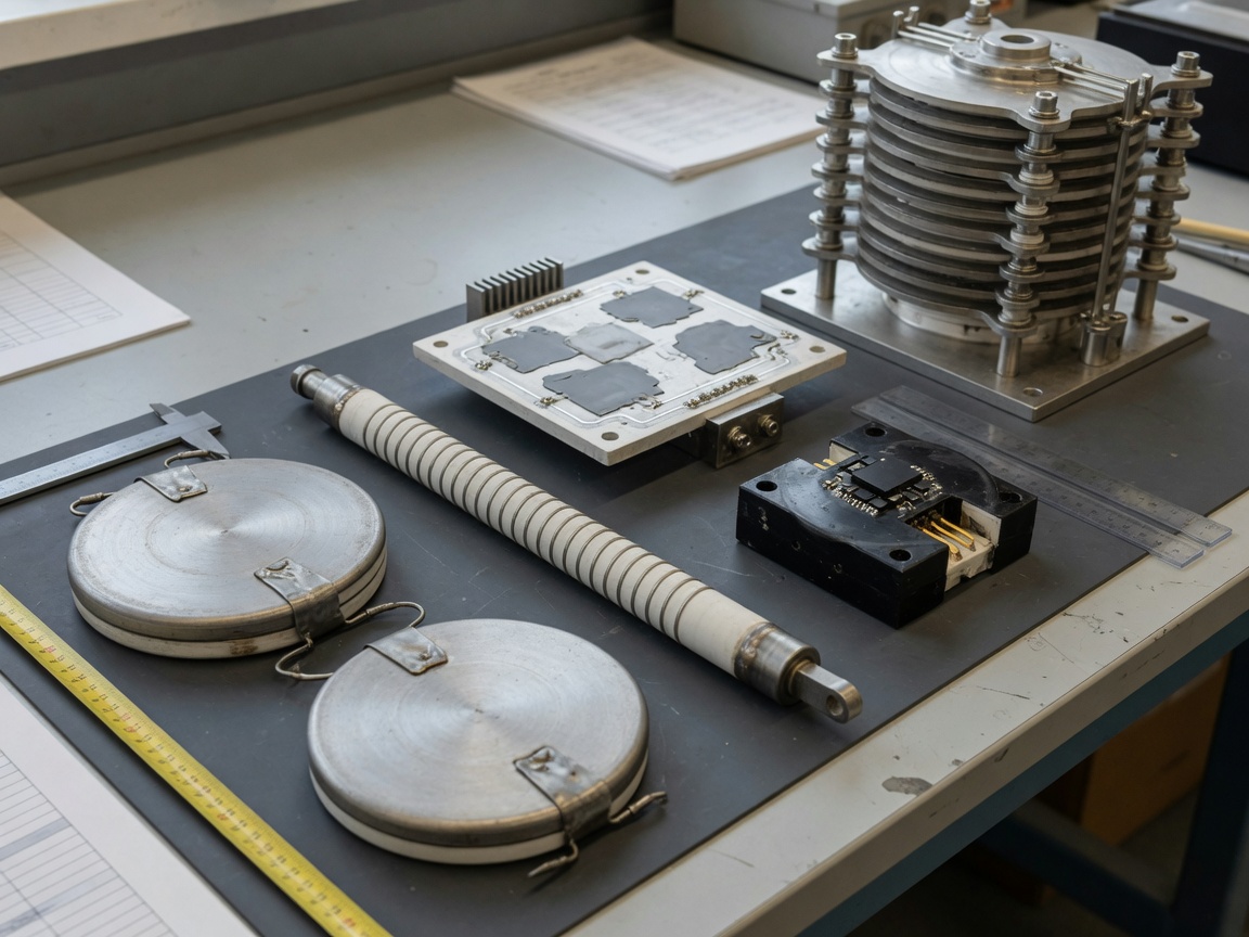
SiC varistors are manufactured in several distinct form factors, each optimized for a specific voltage range, energy handling requirement, or integration context. Selecting the wrong package type — even with the correct electrical ratings — creates mechanical and thermal compatibility problems that shorten service life.
Standard form factors
Disc type (round wafer): The most widely deployed form factor. Disc diameters range from 5 mm to 60 mm. Used extensively in industrial distribution switchgear, motor control panels, and transformer protection. Easy to install in parallel configurations for higher energy ratings.
Rod/column type: Cylindrical stacked elements designed for assembly into high-voltage surge arresters (≥35 kV). Multiple discs are stacked in series inside a housing — this is the dominant structure in transmission-level lightning arrester components used across the US power grid.
Thick-film SiC: Screen-printed SiC layers on ceramic substrates, suitable for PCB-level integration. Response times can be pushed below 1 ns in optimized designs, making these applicable as electrostatic discharge protection elements in communication equipment.
SiC + ZnO hybrid composite: A newer category combining SiC grain matrix with ZnO dopants to improve the nonlinearity coefficient (α) to the range of 25–40, approaching pure ZnO performance while retaining SiC's superior high-temperature stability. Based on recent case studies from power electronics manufacturers, hybrid units demonstrated 18% longer service life under repetitive 8/20 µs surge testing versus single-material SiC discs.
High-voltage encapsulated modules: Hermetically sealed assemblies rated for 35 kV to 500 kV, used in substations, rail traction systems, and offshore wind collection networks. These integrate current-limiting resistor functionality and thermal management directly into the package.
Choosing a form factor by application
For PCB-level transient voltage suppressor needs below 1 kV, thick-film SiC or hybrid SMD varistors are the practical choice. Industrial power line protection components in the 1–35 kV range typically use disc-type devices in parallel arrays. Transmission-level installations exclusively use column/rod assemblies or encapsulated high-voltage modules. The boundaries between these categories are relatively firm — trying to apply a disc-type device in a column arrester application, or vice versa, creates safety and reliability problems that no amount of derating can fully address.
SiC vs. MOV vs. ZnO: side-by-side specification comparison
One persistent gap in most technical resources is a quantitative, head-to-head comparison of SiC varistors against metal oxide varistors (MOVs) and ZnO-based devices. The table below consolidates representative values drawn from manufacturer datasheets and 2026 industry benchmarks. Use this as a baseline for your initial screening — not a substitute for device-level datasheet review.
| Parameter | SiC varistor | Metal oxide varistor (MOV) | ZnO varistor |
|---|---|---|---|
| Nonlinearity coefficient (α) | 3–7 | 25–60 | 30–70 |
| Clamping voltage ratio (Vclamp/V1mA) | 1.8–3.0× | 1.5–2.0× | 1.3–1.8× |
| Peak surge current (Imax, 8/20 µs) | 5–100 kA (HV modules) | 0.5–70 kA | 1–100 kA |
| Energy rating (J/cm³) | 15–40 | 50–200 | 60–250 |
| Operating temperature range | -55°C to +200°C | -40°C to +125°C | -40°C to +150°C |
| Response time | <1 µs (disc); <1 ns (thick-film) | <1 ns – 25 ns | <1 ns – 25 ns |
| Primary voltage range | 1 kV – 500 kV | 14 V – 6 kV | 20 V – 70 kV |
| Aging under repetitive surges | Slow degradation; stable at HV | Moderate; V1mA shifts with surge count | Low-moderate; superior to SiC at LV |
| Typical cost (relative) | Medium–High (HV modules: high) | Low–Medium | Medium |
What the data actually tells you
The table reveals a clear pattern: SiC varistors have a lower nonlinearity coefficient than ZnO and standard MOVs, which means their clamping voltage ratio is less sharp. In low-voltage applications (below 1 kV), this is a genuine disadvantage — ZnO-based semiconductor protection devices offer tighter clamping and higher energy density. However, at transmission voltage levels (≥220 kV), SiC's thermal stability and proven reliability under large-energy impulses remain unmatched. Of course, there are situations where a hybrid SiC/ZnO approach bridges this gap effectively.
How to select the right silicon carbide varistor: engineer's parameter guide
Proper selection requires working through a defined sequence of parameters. Skipping steps — particularly confusing system voltage with V1mA — is the leading cause of either under-protection or unnecessary derating costs.
Step-by-step selection process
- Define the maximum continuous operating voltage (MCOV). This is the highest RMS voltage the varistor will see continuously. The varistor's V1mA must be ≥ 1.2× MCOV to avoid thermal runaway under normal operation.
- Determine peak surge current (Imax). Use the expected 8/20 µs waveform current from your surge threat model. For US residential/commercial applications referencing IEEE C62.41, Category C locations see up to 10 kA. Industrial and utility applications may require 40–100 kA rated devices.
- Calculate required energy absorption capacity. Estimate joule rating from E = 0.5 × C × V² or from system fault energy data. Apply a 2× safety margin. Devices with insufficient energy ratings fail catastrophically rather than gracefully.
- Verify clamping voltage against equipment insulation level (BIL). The varistor clamping voltage at Imax must fall below the basic insulation level (BIL) of the protected equipment by at least a 20% protective margin.
- Select package type. Match form factor to installation environment: disc arrays for industrial switchgear, column assemblies for HV arresters, SMD thick-film for PCB electrostatic discharge protection, and encapsulated modules for outdoor substation use.
- Check power dissipation. Continuous power dissipation under normal leakage must remain within the device's thermal rating for the mounting configuration. Inadequate heatsinking accelerates aging even without surge events.
Common selection errors to avoid
Actual testing and field reports consistently show two recurring mistakes. The first is selecting V1mA too close to MCOV — leaving zero thermal headroom and causing the device to self-heat progressively until it fails. The second is under-specifying Imax based on calculated averages rather than worst-case transient events. In installations near overhead utility lines in lightning-prone regions of the US (Florida, Texas, the Great Plains), applying IEEE C62.41 worst-case values rather than statistical averages is not conservatism — it is basic engineering practice.
Real-world applications: EV charging, solar inverters, and industrial drives
Abstract specifications only mean so much. Examining where silicon carbide varistors are actually deployed — and how they perform — provides the engineering context that specification sheets cannot.
EV charging stations (DC fast chargers)
A 2026 deployment case study from a US-based Level 3 DC fast charging network (150 kW per station, 480 V three-phase input) illustrates the challenge well. The stations were experiencing MOV failures at roughly 18-month intervals due to repetitive switching transients from the local utility grid combined with occasional nearby lightning events. The replacement design used SiC/ZnO hybrid disc varistors at the AC input (V1mA = 750 V, Imax = 40 kA) in parallel with TVS diode arrays at the DC bus output. Post-installation monitoring showed zero varistor failures over a 14-month follow-up period. The higher clamping voltage of the SiC hybrid was acceptable given the BIL margin of the input transformer.
Solar inverters and energy storage systems
In utility-scale solar installations, string inverters in the 50–250 kW range require power line protection components rated for 1,000–1,500 V DC at the PV array input. SiC varistors with V1mA in the 1,200–1,500 V range are well matched to this voltage domain — a range where standard MOVs lack sufficient energy density and ZnO devices begin to show accelerated aging in high-temperature enclosure environments (ambient + self-heating regularly exceeds 85°C in field conditions). The 2026 trend toward 1,500 V DC system architectures in utility solar is specifically driving renewed demand for high-voltage clamping devices in the SiC category.
Industrial motor drives
Variable frequency drives (VFDs) used in pump, compressor, and fan applications generate steep-fronted voltage transients (dV/dt up to 10 kV/µs) on motor terminals due to IGBT switching. Installing disc-type silicon carbide surge protectors on the output bus — in coordination with output reactors — has been shown in industrial case studies to reduce insulation stress on motor windings by 35–50%, extending motor rewind intervals from 3–4 years to 6–8 years in high-cycle applications.
Failure modes, degradation, and predictive replacement
Understanding how silicon carbide varistors fail is just as important as knowing how to select them. Most field failures are not sudden catastrophic events — they are the end result of slow, measurable degradation that predictive maintenance programs can detect before it becomes a problem.
Primary failure mechanisms
Thermal runaway: The most critical failure mode. As a SiC varistor ages, its leakage current at rated voltage gradually increases. Higher leakage → more self-heating → further resistance reduction → more leakage. This positive feedback loop can terminate in a catastrophic short-circuit or open-circuit failure within hours once it begins. Thermal runaway is almost always preceded by a detectable period of elevated leakage current — which is why periodic leakage current measurement is the cornerstone of varistor health monitoring.
Aging under repetitive surges: Each surge event deposits energy into the device and subtly shifts the grain-boundary characteristics. V1mA drifts downward over time. Industry data suggests SiC disc varistors can sustain approximately 1,000–5,000 8/20 µs pulses at 50% of rated Imax before V1mA degrades by more than 10%. Devices subjected to surges exceeding 80% of rated Imax show measurable degradation within 100–200 events.
Mechanical cracking: Thermal cycling between surge events and ambient conditions generates mechanical stress at grain boundaries. Disc-type devices in outdoor installations are particularly vulnerable. Crack propagation reduces effective cross-sectional area, increasing current density and accelerating thermal failure.
Predictive replacement guidelines
Based on field maintenance programs at US utility substations, a reasonable predictive replacement framework combines three indicators: (1) leakage current at rated voltage exceeding 150% of initial datasheet value; (2) V1mA drift greater than ±10% from initial value; (3) calendar-based replacement at 10–15 year intervals in moderate surge environments, or 5–8 years in high-exposure locations (coastal, lightning-prone regions). Using surge counter accessories integrated into arrester assemblies allows event-based retirement criteria rather than purely calendar-based replacement — a more cost-effective approach for large fleets.
Regulatory compliance: UL 1449, IEC 61643, and US market requirements
Surge protection devices sold in the US market must navigate a specific set of regulatory requirements. Specifying a technically superior component that lacks the correct certifications creates procurement and liability complications that engineers and procurement teams consistently underestimate.
UL 1449 (US standard)
UL 1449 is the primary US standard governing surge protective devices (SPDs) for use on 120/240 V to 1,000 V AC systems. The current edition (4th edition) covers SPD types 1 through 4, with performance categories defined by voltage protection rating (VPR), short-circuit current rating (SCCR), and nominal discharge current (In). A silicon carbide varistor incorporated into an SPD assembly must support the VPR and In claims of the complete device. Critically, UL 1449 requires end-of-life indication for Type 1 and Type 2 SPDs — a requirement that interacts directly with the thermal runaway failure mode described above.
IEC 61643 and international alignment
For products sold into both US and international markets, IEC 61643-11 (low-voltage SPDs) and IEC 61643-21 (SPDs for telecommunications) are the relevant international benchmarks. While UL 1449 and IEC 61643 are not fully harmonized, the 2026 landscape shows increasing cross-referencing between the two frameworks, particularly as US-based solar and EV infrastructure projects involve international supply chains. Devices carrying both UL and IEC marks simplify global procurement significantly. For high-voltage applications (above 1 kV), IEC 60099-4 governs metal-oxide surge arresters — the high-voltage counterpart to the low-voltage SPD standards, and the primary compliance document for SiC-based lightning arrester components in transmission applications.
For a comprehensive technical reference on varistor standards and operating principles, the silicon carbide varistor overview on Wikipedia provides a useful starting foundation, though device-specific compliance always requires consulting the applicable UL or IEC standard directly.
Frequently asked questions
Q: What is the main difference between a silicon carbide varistor and a metal oxide varistor?
A: The core difference is nonlinearity. MOVs (typically ZnO-based) have a nonlinearity coefficient of 25–70, producing sharper clamping at lower residual voltage. SiC varistors have α values of 3–7, making them better suited for ultra-high-voltage applications (≥220 kV) where thermal stability and large-energy absorption matter more than tight clamping ratios.
Q: How do I know when a silicon carbide varistor needs to be replaced?
A: Monitor leakage current at rated voltage. If it exceeds 150% of the initial datasheet value, or if V1mA has drifted more than 10% from baseline, replace the device. Calendar-based replacement every 5–15 years (depending on surge exposure) is a practical fallback when monitoring is not installed.
Q: Are SiC varistors still relevant in 2026, or has ZnO completely replaced them?
A: SiC varistors remain the preferred technology for power systems above 10 kV, where their thermal stability and large-energy handling are superior. ZnO dominates the low-voltage segment below 1 kV. In the 1–35 kV range, SiC/ZnO hybrid devices increasingly offer a practical middle ground for 2026 applications.
Q: What certifications should I require for silicon carbide varistors used in US installations?
A: For low-voltage SPD assemblies (≤1,000 V AC), UL 1449 4th edition listing is the minimum US market requirement. For high-voltage transmission applications, IEC 60099-4 is the governing standard. Products with both UL and IEC marks simplify cross-market procurement and simplify AHJ approval in US projects.
Q: Can a silicon carbide varistor be used for electrostatic discharge (ESD) protection on PCBs?
A: Yes, but only in thick-film SiC form. Bulk disc-type SiC varistors are too slow and physically too large for PCB-level ESD protection. Thick-film SiC devices with response times below 1 ns are a viable choice, though TVS diodes and multilayer varistors typically offer better clamping precision for most PCB ESD scenarios below 100 V.
In summary, the silicon carbide varistor remains a technically indispensable component in high-voltage electrical surge suppression — particularly as 2026 trends in EV infrastructure, utility-scale solar, and industrial power electronics push operating voltages higher and demand greater thermal resilience from every protection component in the system. Selecting and maintaining these devices correctly, with attention to the parameters and compliance requirements outlined in this guide, is the difference between robust long-term protection and a failure mode waiting to occur.
Key words:
More Events
Online message
* Note: Please be sure to fill in the information accurately and keep the communication open. We will contact you as soon as possible.

Hotline 7*24 hours

Address: No. 888, Weihui Road, Huilong Town, Qidong City
Add me on WeChat